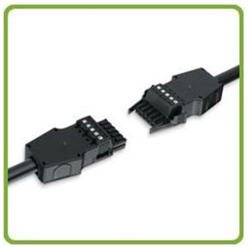


The WINSTA® MAXI connector is designed as 5-pole power supply connector with a maximum conductor cross section of 6 mm2and rated current of 32A. It has been designed to be used in conjunction with WINSTA distribution boxes. Furthermore, it can also be used to minimize the drop voltage over longer cable runs.

Secure Payments are easier than ever! Eway’s payment solutions

Delivery Option’s, you choose from our list of delivery partners

Manufactures warranty on all Cableaway sold products.
Cableaway WINSTA MAXI
WINSTA® MAXI - For a higher performance
The WINSTA® MAXI connector is designed as 5-pole power supply connector with a maximum conductor cross section of 6 mm2and rated current of 32A. It has been designed to be used in conjunction with WINSTA distribution boxes. Furthermore, it can also be used to minimize the drop voltage over longer cable runs.
Product profile
WINSTA® MAXI connectors, Series 831
•The power required for upstream loads benefits from a 7A higher supply current, when compared to the currently available WINSTA® MIDI series.
•No additional fuse protection is required, even though the cross section is reduced from 6 mm2 (WINSTA® MAXI) to 4 mm2 (WINSTA® MIDI), when the output cables are less than 3 meters in length.
•WINSTA® MIDI and WINSTA® MAXI cannot be mated together, due to the inherent safety of their unique coding design.
•Time and cost saving CAGE CLAMP®S technology for push-in connection of stripped solid wires and ferruled stranded wires.
•100 % protection against mismating.
•Number of poles: 5 poles
•Wire range: 5 x 0.5 mm2 - 6 mm2
•Rated voltage: 400 V/6 kV/3
•Rated current: 32A
Preparation
1.Sheath removal length = 80 mm
2.Stripping length = 13 mm
3.Advance PE conductor = 10 mm
For the connection of flexible conductors, manipulate clamp spring using screwdriver (blade width 5.5mm) and insert the stripped conductor to the stop.
Strain relief mounting
Unscrew strain relief from the lower part of the housing . . .
. . . and latch wired plug-in connector onto the lower part.
tighten strain relief with screwdriver.
Wired plug-in connector in the lower part of the strain relief housing
Latch on upper part of strain relief housing
Marking
The printed marking of the plug-in connector is clearly visible in the opening of the strain relief housing.
Complete and plug together